Velocity triangle or diagram of centrifugal pump How pressure increases in centrifugal compressor? Solved question 3 (a) sketch a velocity diagram with
Centrifugal Fan Diagram
How to make a simple centrifugal fan Centrifugal pump Centrifugal pump diagram
How to draw velocity triangles for turbines at how to draw
Introduction to centrifugal pumps pdfIndustrial centrifugal pumps Velocity triangle for centrifugal fan and blowerVelocity triangle or diagram of centrifugal pump.
Velocity triangles diagram for impeller of centrifugal pumpSolved 1) draw the velocity diagram for a centrifugal The velocity triangles at the runner of a pump-turbine in turbine modeCentrifugal pump diagram 2d.

Centrifugal plots velocity goal trajectories results
Centrifugal pump design and analysis : skill-lyncCentrifugal pump working principle – studiousguy Types of pumps archivesWorking principle of centrifugal pump.
Pump centrifugal working parts principle types main application advantages its components disadvantages suction valve foot strainer pipe mechanical casing pressureVelocity pump centrifugal triangle Pumps pump sketch sectional centrifugal radial types parts marine archives showing tag paintingvalleyCentrifugal pump flow diagram.

Velocity diagram of centrifugal compressor
Velocity triangle of centrifugal pump || centrifugal pumpCentrifugal fan diagram Un évènement style linternet centrifugal pump formula prophète clartéExploded view sears centrifugal pump diagram parts list for model.
Velocity equation triangleCentrifugal velocity triangle fan impeller inlet blower outlet blades types different 1) centrifugal pump constructionCentrifugal pump cutaway diagram.

Velocity diagram and work done by impeller
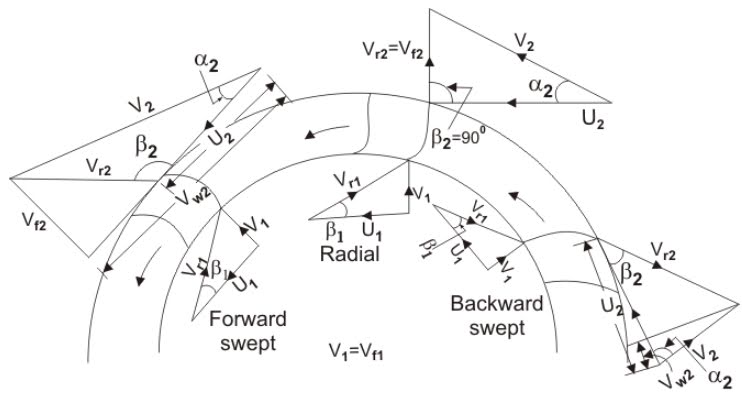
Centrifugal fan scheme and velocity triangles to inlet and outlet ofVelocity impeller diagram work done Centrifugal compressor velocity increases radial traingle.
.


Centrifugal Pump Working Principle – StudiousGuy

Centrifugal Fan Diagram

Velocity Triangle or Diagram of Centrifugal Pump - Work Done

Exploded View Sears Centrifugal Pump Diagram Parts List For Model | My

Solved QUESTION 3 (a) Sketch a velocity diagram with | Chegg.com

Centrifugal Pump - Working Principle, Main Parts with Application
VELOCITY TRIANGLE FOR CENTRIFUGAL FAN AND BLOWER - ENGINEERING APPLICATIONS

Centrifugal pump design and analysis : Skill-Lync